Vertical Take-Off and Landing Rocket
April-August 2020
Overview:
The objective of this project was to build and code from scratch a 3D printed rocket to take off and then land while maintaining a vertical orientation for the duration of the flight. With this project, I wanted to gain some experience with Guidance, Navigation, and Controls (GNC). I worked on this project with a friend: Shihao Cao. He provided the flight software structure and provided invaluable advice for hardware debugging.
Hardware:
This rocket uses two counter-rotating racing drone motors for its propulsion system. The counter-rotating motors allow for roll control via differential throttle, which will result in a net roll moment due to the conservation of angular momentum. In order to get control in the yaw and pitch axes, servo-driven thrust vector control (TVC) fins were utilized to direct the exhaust from the bottom motor.
The body of the rocket is fully 3D printed. In total, there are 26 separate parts that need to be printed.
Below is a labeled diagram of the rocket. The lithium-polymer battery is hidden by the flight computer.

Below is a video that shows the TVC fins in action inside of the thrust structure
Electronics:
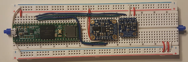
The flight computer contains a Teensy 3.6 for the microcontroller, a BNO055 Inertial Measurement Unit (IMU) for acceleration, angular velocity and orientation measurements (the Adafruit sensor has a sensor fusion algorithm built-in for orientation measurement), and a BMP280 barometric pressure sensor for altitude measurements. Below is a picture of the flight computer wired up on a breadboard without the servo and motor connectors.
Simulation:
For this project, I opted to use a PID controller. Initially, I used Matlab to write all of the controls, as well as a physics engine to test the functionality of the controls. This simulation was incredibly primitive: it did not include process noise or sensor noise. I simulated a SpaceX Starhopper-like flight and exported the position and orientation data from the physics engine into Blender to create an animation, which is shown below.
Flight Software:
After writing the controls in Matlab, I had to convert it into C++, so it could run on the Teensy. I had to make many additions when writing this flight software. For example, I used a unit quaternion for reference frame shifts (instead of Euler Angles), which eliminated gimbal locking problems and the discontinuities of Euler angles at 180 degrees. I also wrote a Kalman Filter to combine barometer readings and acceleration readings to get a more accurate altitude reading. From my tests, the Kalman Filter decreased variance in altitude readings by 44%.
Below is a very high-level block diagram of the controls.

Thrust Testing:
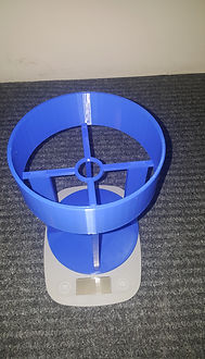
In the Arduino environment, a motor is throttled is by passing in a value between 0 and 180 that will map to some thrust force. The higher the actuation value, the higher the thrust. With the PID controller, a desired thrust force is calculated, which then must be mapped to this 0-180 value. In order to construct this mapping, I needed to do thrust tests where I have the rocket on a test stand, which can measure the delivered thrust at different actuation values. Below are pictures of the thrust stand as well as a video of a thrust test.

Roll Control Testing:
Before doing full flight tests, I wanted to ensure that I had full roll control. Roll control is achieved by spinning the top and bottom motors at different speeds, which will generate a net roll moment on the vehicle. I conducted these tests by hanging the rocket from my ceiling and commanding a constant thrust value. Below are two videos. The video on the left is when I command both motors with the same 0-180 command. In theory, there should be no net moment since the two motors would have equal and opposite angular momenta, however, due to variations between motors in the manufacturing process, this isn't true. The video on the right shows the stabilizing effect of the controller.
Flight Tests:
To date, I have completed 15 flight tests. After the first two tests in which the rocket ended up pointing downwards and thrusted into the ground, causing almost every part to be reprinted, I added in an orientation-based flight termination system, so if the rocket exceeds 60 degrees in the pitch or yaw directions, all thrust is cut. In addition, I printed four extras of every part for quick fixes. Other than this, most of the changes I made were removing bugs in my code (incorrect quaternion to Euler angle conversions, simple sign errors, etc), and tuning my PID values. Below are videos of a few important flights that show progression. They are flights 1, 12, 14, and 15.
Flights 1 (left) and 12 (right)
Flights 14 (left) and 15 (right)
Flight 14 experienced a structural failure, but its orientation controller looked good. Unfortunately, I experienced a loss of vehicle on flight 15. There was a bug with the altitude controller, which led to the constant gain in altitude. The horizontal drift cannot be fixed with the sensors I am using, since no inertial sensor can detect an object moving with a constant velocity. In addition, the time-based flight termination system was set for too long of a time. This was my first flight over 5 seconds, so I couldn't have predicted this bug. After this flight, I chose better values for the time-based flight termination system, added an altitude based flight termination system, and wrote the code to perform a landing.
Below I have shown two additional flights: flights 18 and 23. After flight 18, I had a couple of abnormal tests where the altitude readings were off my almost 3 meters, which were likely caused by winds. After those two tests, I only flew in still wind and focused on softening the landing. And finally after a few hundred hours of effort, flight 23 stuck a landing, bringing this project to a close.
Flights 18 (left) and 23 (right)
Future Plans:
Now that it has been shown that fin-based TVC can provide sufficient attitude control and that it is possible to vertically take off and land autonomously, the next step is scaling up. The rocket should be able to fly vertically to roughly 50m and then land at a pre-programmed location. Some anticipated improvements will be designing a proper PCB for the flight computer rather than using a breadboard, using full-state feedback (which is better for MIMO systems) instead of PID, having live telemetry beamed down to a ground station, and using a GPS to land at the designated landing site.
Ideally, I would also like to start learning about optimal control and implement that into the landing algorithm.